


Concrete as a construction material has been popular since ancient times. Be it the Pyramids of Egypt or the Roman Pantheon, that concrete was a structural material of choice for the mighty civilizations of the yore is well known. In modern times, concrete is used extensively in various kinds of buildings, pavements, stadia, bridges, dams, tanks, pipes, tunnels etc. In fact, concrete is the most used man-made material in the world.
Concrete has high compressive strength, but is remarkably weak in tension (about one-tenth its compressive strength), and as such is usually reinforced with materials that are strong in tension (often steel). Reinforcement solutions to plain concrete in the form of steel bars have existed and been studied for a long time now. A relatively new development however has been the advent of use of fibres as reinforcement to improve the tensile properties of plain concrete and cater to a host of various specific applications of structural concrete. Tremendous research has been done and many projects of varying sizes have been executed in various countries around the globe including India.
Specifically, fibres tend to increase post crack strength, ductility and durability of concrete. Fibres dispersed homogeneously and oriented randomly in the concrete mix work as three dimensional reinforcements. Commonly available fibres include steel fibres, synthetic fibres, glass fibres, aramid fibres and natural fibres. It is to be noted that use of different kinds of fibres are application specific and don’t work as a single pill for all ailments. Of these fibres, steel and synthetic command greater technical and commercial acceptability as compared to others in terms of usage in the field and hence are the primary focus of this article as well.
1.Steel Fibre Reinforced Concrete (SFRC)
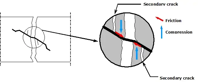
Steel Fibre Reinforced Concrete (SFRC) is defined as a concrete, containing discontinuous discrete steel fibres, which when incorporated in concrete improve its crack resistance, ductility, energy absorption and impact resistance characteristics and offer a long term post crack tensile strength. Particularly under flexural loading, fibres are able to hold the matrix together even after extensive cracking. Thus, steel fibres transform the brittle concrete into a ductile material. Also, unlike traditional steel reinforcement, steel fibres are discontinuous and 3-dimensionally orientated in the concrete matrix. As the concrete cracks they transfer the tension across the crack and guarantee a post crack load bearing capacity while bridging the cracks (See Figure 2). The fibres should be sized in such a way that they cover at least 2 major aggregates of the concrete.
Owing to the enlisted advantages, SFRC is widely used for applications such as industrial floors, foundation slabs, shotcreting, tunnelling and precast elements. Relating to these applications, SFRC is a well established building material and a meaningful alternative to plain or reinforced concrete. Furthermore, a discontinuous form of reinforcement in SFRC aids in resistance to corrosion which is a major problem in conventional reinforced concrete elements.
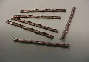
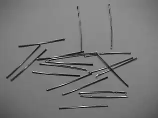
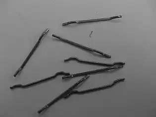
However, the effect of fibres on concrete properties varies to a great extent based on the fibre type. A variety of fibre types are available (Figure 1) based on the choice of materials (high carbon, low carbon), shapes (hooked, crimped) and different sizes. Therefore steel fibre reinforced concrete should never be simplified as a “concrete with steel fibres”. SFRC has to be seen as an engineered material which when added to an appropriate concrete composition according to a suitable fibre type and corresponding dosage meets the given requirements.
1.1 Applications of SFRC
Generally, in structural applications, SFRC should only be used in a supplementary role to inhibit cracking, to improve resistance to impact, to resist dynamic loading and material disintegration. In structural members where considerable flexural and axial tensile stresses occur, such as in beams, columns, suspended/roof slabs etc., steel fibres alone are insufficient and should never be wholly used to replace traditional steel reinforcements. Some of the more appropriate examples (Figure 3) of general structural and non-structural uses of SFRC are listed as follows:-
- Hydraulic structures — Dams, spillways, stilling basins, and sluiceways as new or replacement slabs or overlays to resist cavitation damage
- Airport and highway paving and overlays – Particularly where a thinner-than-normal slab is desired
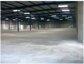
- Industrial floors — For impact resistance and resistance to thermal shock
- Refractory concrete — Using high-alumina cement in both castable and shotcrete applications
- Foundation slabs for residential buildings
- Bridge decks — As an overlay or topping where the primary structural support is provided by an underlying reinforced concrete deck
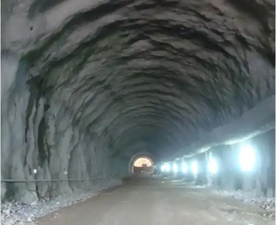
- In shotcrete linings — For underground support in tunnels and mines, usually with rock bolts
- In shotcrete coverings — To stabilize above ground rock or soil slopes, e.g., highway and railway cuts, and embankments
- Thin shell structures — shotcrete “foam domes”
- Explosion-resistant structures — Usually in combination with reinforcing bars
- A possible future use in seismic-resistant structures


1.2 Performance characterization for SFRC
One needs to understand that although all the different types of steel fibres mentioned above work in improving the properties of concrete in some way, they do so with varying degrees of performance. For example, not all of them fulfil the requirements on field and lack technical details that a designer needs to assess the fibre performance in the structure. The idea is to have an “engineered fibre” not just any alternative to make the solution work in a manner it is envisioned to in the structure. Some of the important parameters are listed below:-
- Shape (straight, hooked, undulated, crimped, Twisted, coned)
- Length (12.7 to 63.5 mm)
- Diameter (0.4 to 1.0 5mm)
- Tensile Strength (1000 – 2500 N/mm²)
Effect of Fibre Parameters
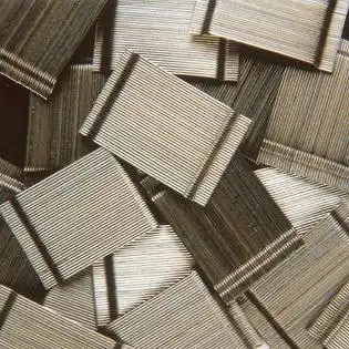
There are several ways in which one can quickly ascertain the performance of various fibre types. According to Shape, hooked end fibres have been time tested and have proved to be the most economical form of anchorage improving the fibre performance compared to straight fibres and of various other shapes. Also, collated or glued fibres have been specially developed by some manufacturers to enable a homogenous fibre distribution in concrete and prevent balling of fibres while mixing with concrete.
Another one of the most important performance parameters for fibres happens to be Aspect Ratio. Aspect ratio in a layman’s term is the ratio of Fibre Length to Diameter. As length of the fibre increases, the region covered by fibre in the concrete also increases. Similarly, with the reduction of fibre diameter, the number of fibres per unit weight increases, thereby increasing the network of wires per unit volume of concrete. Refer following typical data (Table 1), which compares three different types of fibres of a particular manufacturer based on aspect ratio. These properties will vary from one steel fibre manufacturer to manufacturer.
| 3D 45/50BL | – l/d = 45 | L = 147 m / kg |
| 3D 65/60BG | – l/d = 65 | L = 200 m / kg |
| 3D 80/60BG | – l/d = 80 | L = 276 m / kg |
This simply means that a higher aspect ratio has a larger network of fibres compared to lower aspect ratio fibres for the same level of performance. This in essence would also translate to lower dosages for higher aspect ratio fibres. The usual amount of steel Fibres ranges from 10 kg/m³ for higher aspect ratios (80), to 80 kg/m³ for lower aspect ratio (50). Thus, simply comparing a fibre dosage with another fibre dosage would not lead to the right conclusions as it would depend on a number of variables. Conversely, performance for the same quantity of different fibres would be different, as illustrated in Figure 3.

Tensile strength of fibres also plays a major role in pinning the performance of SFRC. The strength should be large enough to undergo substantial yielding and not snap at the crack interface. More important then becomes the tolerance levels of fibre components as it is essential to guarantee the minimum tensile strength for each and every fibre strand to achieve the required performance.
Table 2 gives a comparison on the performance of SFRC Slab on grade using various fibre geometries, loadings 3 T to 7 T UDL on a 5 % CBR sub-base. The dosage of fibres varies depending on the aspect ratio, tensile strength, anchorage etc. Please note that these are case specific results and presented for ease of understanding of the concept only.
| S No. | Aspect Ratio ( L/D) | Type | Length mm | Diameter mm | Length (m/kg) | Dosage (kg/m3) |
| 1 | 48 | Loose | 50 | 1.05 | 147 | 31.5 |
| 2 | 67 | Glued | 60 | 0.9 | 200 | 20 |
| 3 | 80 | Glued | 60 | 0.75 | 276 | 15 |
1.3 Practical aspects of SFRC
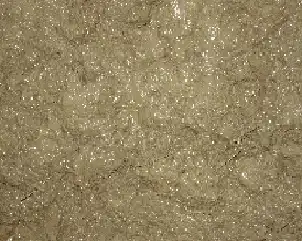
One of the basic concerns in SFRC is to introduce sufficient volume of fibres to be uniformly dispersed (Figure 5 ) to achieve the desired improvements in mechanical behaviour, while retaining sufficient workability in the fresh mix to permit proper mixing, placing and finishing. Several procedures for proportioning SFRC mixes are available, which emphasize the workability of the resulting mix. Smaller dosages of Steel fibres in concrete usually do not entitle too many changes in the design mix as the workability of concrete is not severely affected by fibre addition. However, there are some considerations that are particular to SFRC. In general, SFRC mixes contain higher ratios of fine to coarse aggregates than in ordinary concrete, and so the mix proportioning procedures that apply to conventional concrete may not be entirely applicable to SFRC. In addition, to improve the workability of higher fibre volume dosages, super-plasticizers are often used, in conjunction with air entrainment.

Most commonly, when using a transit mixer or revolving drum mixer, the fibres should be added last to the wet concrete. The concrete alone, typically, should have a slump of 15-25 mm greater than the desired slump of the SFRC or 50-60 mm in case of SFRS. The use of collated/Glued fibres held together by a water-soluble component which dissolves during mixing largely eliminates the problem of clumping/Balling. The finishing operations with SFRC are essentially the same as for ordinary concrete, though perhaps more care must be taken regarding workmanship.
1.4 Concluding remarks on SFRC
Steel fibres have been in prevalence elsewhere in the world for over 3 decades in various applications. Consequently a lot of international guidelines exist which detail the technical design aspects of SFRC structures. Reduced construction time, simplified reinforcement drawings, no stockyard, enhanced job safety and increased durability and ductility are only some main benefits of SFRC, which are mentioned in that context. At the same time it needs some special knowledge to understand, design and execute this special building material.
2.Synthetic Fibre Reinforced Concrete (SYNFRC)
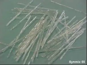
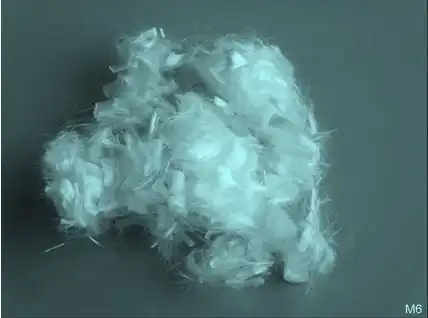
Synthetic fibres are artificial fibres resulting from petrochemical and textile industries. Various types of fibres that have been tried in concrete include acrylic, aramid, carbon, nylon, polyester, polyethylene and polypropylene. It should be noted that polypropylene fibres have found commercial applications and have been the subject of extensive reporting. These fall under the category of micro synthetic fibres.
About a decade back, suppliers started to offer macro synthetic fibres. Some applications for mining and Precast-elements were executed with this quite new construction material. Macro synthetic fibres sometimes have dimensions comparable to steel fibres but are nevertheless very different in material properties. Still, there are some definite applications where plastic fibres supersede other materials in terms providing benefits to the concrete.
2.1 Micro SYNFRC and its applications
Micro fibre concrete with polypropylene fibres are mainly used to reduce plastic shrinkage in fresh concrete. During the hardening process of concrete, dissipation of heat of hydration of concrete coupled with evaporation of water induces tensile stresses. Beyond a threshold limit of these stresses, micro cracks start developing in the concrete. Micro fibre concrete with polypropylene fibres reduces effective the early shrinkage behaviour in the first 10 hours of pouring. The reason is that these types of fibres are able to hold back some water and slow down the evaporation process. They also are able to pick up some limited tensile stresses especially in the early age. These types of fibres work better to reduce plastic shrinkage cracks and are often added in addition to the reinforcement of concrete.
Another application of these fibres lies in improving the fire resistance behaviour of concrete structures at very high temperatures. Concrete as such in itself is a good fire resistant material. However, under extremely high temperatures, concrete tends to spall off due to entrapped vapours pushing their way out of dense pore structure of concrete in a fire event. Addition of micro fibres in the concrete ensures that as these fibres melt, they create open channels in the concrete pore structure which allows the built up vapours to escape, thereby releasing the internal pressures and preventing the spalling.
2.2 Macro SYNFRC and its applications
Macro fibre concrete with polypropylene fibres are mainly used in lightly loaded applications where the concrete behaviour is calculated as un-cracked concrete just to improve the concrete in terms of their crack behaviour and to improve the resistance against the thermal shrinkage process.
The reason that these fibres are mainly used in lightly loaded structures is that in the case of heavily loaded structures, these fibres tend to creep and hence a design in the cracked state under long term loadings does not save the structure in the event of a failure. Macro synthetic fibres do not corrode. Hence in case of macro fibres, no rusty spots appear at the surface. Additionally macro synthetic fibres can be effectively used in applications like temporary linings such as for mines when larger deformations are allowed and acceptable. However, it should be noted that due to low Young’s Modulus of macro synthetic fibres, crack widths are very significant (> 0.5 mm) before fibres start to work.
2.3 Comparison between SYNFRC and SFRC
Material Properties
| Material / Fibre Type | Unit weight (gm/cc) | Length (mm) | Diameter (mm) | Elastic modulus (GPa) | Tensile strength (MPa) | Melting Point (oC) |
| Steel Micro Synthetic Macro Synthetic Hardened concrete | 7.85 0.91 0.91 1.8-2.4 | 30-60 6-20 30-65 – | 0.5-1 0.015-0.030 0.5-1 – | 210 3-10 3-10 10-45 | 500-2000 200-600 200-600 2-4 | 1500 165 165 – |
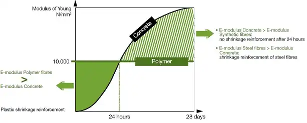
Table 3 illustrates the main differences in terms of the material and the material properties of steel and plastic fibres. In general, the young’s modulus of these plastic fibres is lower than that of hardened concrete, which limits their use in permanent structures and structural applications unless of course if higher deformations are acceptable for the structure. When the concrete is in fresh state, it’s young’s modulus is less or comparable to those of micro synthetic fibres and hence such fibres work well as plastic shrinkage reinforcement. However, beyond the fresh state, such fibres add no significant value (Figure 7).
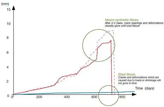
It is to be noted that macro synthetic fibres start losing their mechanical properties at 50°C which has also to be taken into consideration when fire resistance is a given requirement. Furthermore, their long term behaviour shows a high tendency to creep behaviour (Figure 8) owing to their visco-elastic behaviour. Creep is the increase in extension of a material under constant load. The deformation of the fibre is not only time-dependant, but also temperature-dependant.
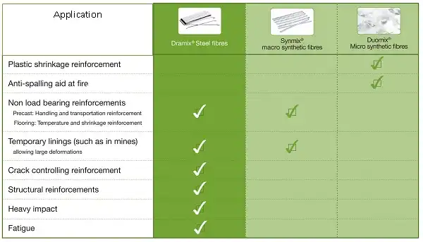
Application areas
2.4 Concluding remarks on SYNFRC
Synthetic fibres hold on their own in terms of the benefits they provide to concrete at various stages of construction and application types. Micro fibres provide excellent solution to plastic shrinkage problem in concrete and improve the fire resistance of concrete while macro fibres find appropriate applications with higher structural deformations and lighter loads. While a number of options are available on the type of fibre to be used, it is very important to choose the right fibres for the appropriate application. Care should be taken to design the structure for the appropriate load coming over it fully understanding the limitations of the fibres that are involved. Though the right design of the structure is done and the fibre is chosen, much lies in the hands of the engineer that executes the job.
References
- Shah, S. P., and Rangan, B. V., “Fibre Reinforced Concrete Properties,” ACI JOURNAL, Proceedings, Vol. 68, No. 2, Feb. 1971, pp. 126-135
- Hoff, George C., “Use of Steel Fibre Reinforced Concrete in Bridge Decks and Pavements,” Steel Fibre Concrete, Elsevier Applied Sciences Publishers, Ltd., 1986, pp. 67-108.
- Ramakrishnan, V.; Coyle, W. V. ; Kopac, Peter A. ; and Pasko, Thomas J., Jr., “Performance Characteristics of Steel Fibre Reinforced Superplasticized Concrete,” Developments in the Use of Superplasticizers, SP-68, American Concrete Institute, Detroit, 1981, pp. 515-534.
- Johnston, C. D., “Steel Fibre Reinforced Mortar and Concrete—A review of Mechanical Properties,” Fibre Reinforced Concrete, SP-44, American Concrete Institute, Detroit, 1974, pp. 127-142.
- Morgan, D. R.; McAskill, N.; Richardson, B. W.; and Zellers, R. C., “A Comparative Evaluation of Plain, Polypropylene Fibre, Steel Fibre, and Wire Mesh Reinforced Shotcrete,” Transportation Research Board, Washington D. C., Jan. 1989.
- Banthia, N., and Ohama, Y., “Dynamic Tensile Fracture of Carbon Fibre Reinforced Cements,” Proc., Int’l Conf. on Recent Developments in FRC, Cardiff, Sept. 1989, pp. 251-260.
- Jakel, G. R., “Fibre Reinforced Concrete Products and Their Formation; Polyesters, Cellulose Pulp,” U.S. Patent #US3899344, Aug. 1975.
- Nagabhushanam, M.; Ramakrishnan, V.; and Vondran, G., “Fatigue Strength of Fibrillated Polypropylene Fibre Reinforced Concrete,” Transportation Research Record 1226, National Research Council, Washington D.C., 1989, pp. 36-47.
- Deutscher Beton- und Bautechnik-Verein e.V.: DBV-Merkblatt „Stahlfaserbeton“. Fassung Oktober 2001
- Ganesh P. Chaudhari, Design Of Durable SFRC Industrial floor ACI Seminar 2008 , Rantagiri, india
- Österreichische Vereinigung für Beton- und Bautechnik „Richtlinie Faserbeton“ Fassung Juli 2008
- DIN EN_14889-1: Fasern für Beton, Teil 1: Stahlfasern – Begriffe, Festlegungen und Konformität
- DIN EN_14889-2: Fasern für Beton, Teil 1: Polymerfasern – Begriffe, Festlegungen und Konformität
- Die Bibliothek der Technik Band 136: “Stahlfaserbeton: Ein neuer Baustoff und seine Perspektiven”, [Hochttief/Bekaert]
- RILEM TC 162-TDF: “Test and design methods for steel fibre reinforced concrete Background and experiences-”, Chairlady L. Vandewalle, March 2003
- The Concrete Society: Technical Report No.63 “Guidance for the design of steel-fibre-reinforced concrete”, March 2007
- G.Vitt, Combined reinforcement – practical experiences, BEFIB 2008, 17-19 September 2008, Chennai
- A. Lambrechts, brochure: Steel- and Synthetic Fibre Reinforced Concrete
- Bekaert, brochure: Recommendations for handling, dosing and mixing

