Structural health monitoring is a method of recording, processing and evaluating measurement data to detect structural changes, damage and critical stress levels at an early stage. This is designed to ensure functional capability, safety and smooth operation while at the same time reducing technological and financial outlay. The structural health monitoring system consists of sensors located at carefully selected positions throughout the building, data transmission equipment and a server for data collection and control. Within the server analysis software containing a special mathematical model is present. The server connects to a local operator desktop application and can remotely be viewed and updated. The operator can monitor the building at real-time and immediately see the status of the building. The design, fabrication, and construction of smart structures are one of the ultimate challenges to engineering researchers today. Because they form the essence of system intelligence, one of the cores of smart structures technology centers around innovative sensors and sensor systems. Structural health monitoring represents one of the primary applications for new sensor technologies.
Structural health monitoring foresees potential problems before they have a chance to cause actual damage. This is all thanks to intelligent sensors that detect even the tiniest of changes to the building or machine structure. This ensures much more than just significantly enhanced safety, because it also allows you to drastically reduce maintenance costs – for example, by replacing specific, individual components potentially susceptible to damage before they can affect other components.
The system development process contains three stages: design, construction and maintenance:
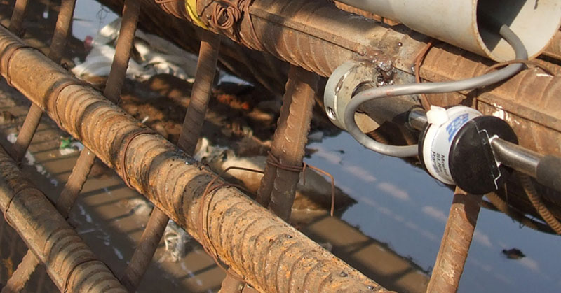
- In the design stage threats are modelled, the required monitoring parameters are identified and mathematical and computer models are generated. In this stage initial rules are set up which determine the sensor type and location. Depending on the required parameter, sensors can be installed embedded in the concrete, on an armature or in special housings.
- By monitoring the building for a period of time and evaluating the results, the mathematical and computer models developed in the design stage are verified and corrected in the monitoring software when needed.
- The maintenance stage is where the building operators take control of the monitoring system and use the specially developed software for building operation and maintenance. The software allows the operators to immediately see the status of the building.
A special structural monitoring software package, SODIS Building M, is developed and marketed by NPO SODIS. This software allows the structural monitoring system to make complex analysis of different measurements and display the monitored results in real time. The software package is used to define the complicated rules obtaining the building status. After this definition, the software is used in the operation of the structural monitoring system by making decisions on the real-time state or condition of the building. Each building requires its own mathematical model, its own set of rules and the software is therefore tailored to each building. For the operator of the building, the software can work with 2D and 3D models of buildings and structures.
Different types of Sensors for Structural Health Monitoring
Rapid advances in sensors, wireless communication, Microelectromechanical Systems (MEMS), and information technologies have the potential to significantly impact SHM. To assist in dealing with the large amount of data that is generated by a monitoring system, on-board processing at the sensor allows a portion of the computation to be done locally on the sensor’s embedded microprocessor. Such an approach provides for an adaptable, smart sensor, with self diagnosis and self-calibration capabilities, thus reducing that amount of information that needs to be transmitted over the network.
Fiber optic sensor
A fiber-optic sensor is a sensor that uses optical fiber either as the sensing element (“intrinsic sensors”), or as a means of relaying signals from a remote sensor to the electronics that process the signals (“extrinsic sensors”). Fibers have many uses in remote sensing. Depending on the application, fiber may be used because of its small size, or because no electrical power is needed at the remote location, or because many sensors can be multiplexed along the length of a fiber by using light wavelength shift for each sensor, or by sensing the time delay as light passes along the fiber through each sensor. Time delay can be determined using a device such as an optical time-domain reflectometer and wavelength shift can be calculated using an instrument implementing optical frequency domain reflectometry. Fiber-optic sensors are also immune to electromagnetic interference, and do not conduct electricity so they can be used in places where there is high voltage electricity or flammable material such as jet fuel. Fiber-optic sensors can be designed to withstand high temperatures as well.
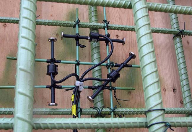
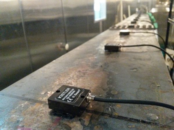
Accelerometer
MEMS (Microelectromechanical Systems) capacitive accelerometers is one of the technologies, which addresses the needs of SHM. Because of the flat amplitude and phase response over a large bandwidth, ruggedness and attractive SWAP characteristics MEMS technology enables the increasing use of vibration sensing for SHM. MEMS accelerometers use capacitive coupling to detect the motion of a suspended proof mass in response to external acceleration. A fabrication process that we utilize “bakes” the MEMS at very high temperatures. This fabrication design guarantees a very good performance repeatability in both – the temperature and the time. Obtained capacitive MEMS devices will measure from very low frequencies (<<1Hz) to high frequencies.
Vibrating wire
A vibrating wire sensor measures the opening of a joint from the stretch of a wire being made to vibrate at acoustical frequency. Since the wire is made of an elastic metal, this kind of sensor can be used as well to measure pulling forces to within a certain range. The applied external force indeed changes the tension on the wire, this changes the frequency. The frequency is measured and indicates the amount of force on the sensor. The load sensor has an integrated electronic system to both activate the vibrating wire as well as to read the frequency. This can be compared to a guitar: animating the strings, creates a vibration and a sound. The sound will be dependent on the tension on the strings.
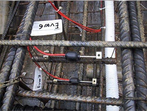
Linear Variable Differential Transformer
Linear Variable Differential Transformer is a common type of electromechanical transducer that can convert the rectilinear motion of an object to which it is coupled mechanically into a corresponding electrical signal. LVDT linear position sensors are readily available that can measure movements as small as a few millionths of an inch up to several inches. The moving element of an LVDT is a separate tubular armature of magnetically permeable material. This is called the core, which is free to move axially within the coil’s hollow bore, and mechanically coupled to the object whose position is being measured. This bore is typically large enough to provide substantial radial clearance between the core and bore, with no physical contact between it and the coil. In operation, the LVDT’s primary winding is energized by alternating current of appropriate amplitude and frequency, known as the primary excitation. The LVDT’s electrical output signal is the differential AC voltage between the two secondary windings, which varies with the axial position of the core within the LVDT coil. Usually this AC output voltage is converted by suitable electronic circuitry to high level DC voltage or current that is more convenient to use.
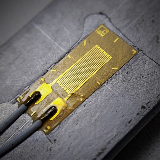
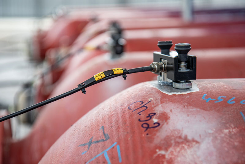
Strain gauge load cell
Strain gauge load cells are the kind most often found in industrial settings. It is ideal as it is highly accurate, versatile, and cost-effective. Structurally, a load cell has a metal body to which strain gauges have been secured. The body is usually made of aluminum, alloy steel, or stainless steel which makes it very sturdy but also minimally elastic. This elasticity gives rise to the term “spring element”, referring to the body of the load cell. When force is exerted on the load cell, the spring element is slightly deformed, and unless overloaded, always returns to its original shape. As the spring element deforms, the strain gauges also change shape. The resulting alteration to the resistance in the strain gauges can be measured as voltage. The change in voltage is proportional to the amount of force applied to the cell, thus the amount of force can be calculated from the load cell’s output. A strain gauge is constructed of very fine wire, or foil, set up in a grid pattern and attached to a flexible backing. When the shape of the strain gauge is altered, a change in its electrical resistance occurs. The wire or foil in the strain gauge is arranged in a way that, when force is applied in one direction, a linear change in resistance results. Tension force stretches a strain gauge, causing it to get thinner and longer, resulting in an increase in resistance. Compression force does the opposite. The strain gauge compresses, becomes thicker and shorter, and resistance decreases. The strain gauge is attached to a flexible backing enabling it to be easily applied to a load cell, mirroring the minute changes to be measured. Since the change in resistance measured by a single strain gauge is extremely small, it is difficult to accurately measure changes. Increasing the number of strain gauges applied collectively magnifies these small changes into something more measurable. A set of 4 strain gauges set in a specific circuit is called Wheatstone bridge.
Inclinometer
An inclinometer is used to monitor subsurface movements and deformations. Typical applications for inclinometers include detecting zones of movement and establish whether movement is constant, accelerating, or responding to remedial measure, checking that deformations are within design limits, that struts and anchors are performing as expected, and that adjacent buildings are not affected by ground movements, verifying stability of dams, dam abutments, and upstream slopes during and after impoundment and monitoring settlement profiles of embankments, foundations, and other structures (horizontal inclinometer). An inclinometer system has two components: (1) inclinometer casing and (2) an inclinometer measurement system.
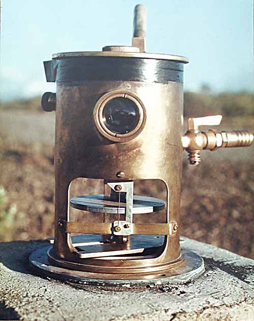
Tilimeter
A tiltmeter is a sensitive inclinometer designed to measure very small changes from the vertical level, either on the ground or in structures. Tiltmeters are used extensively for monitoring volcanoes, the response of dams to filling, the small movements of potential landslides, the orientation and volume of hydraulic fractures, and the response of structures to various influences such as loading and foundation settlement. Tiltmeters may be purely mechanical or incorporate vibrating-wire or electrolytic sensors for electronic measurement. A sensitive instrument can detect changes of as little as one arc second.
Acoustic Emission Sensors
AE sensors (Acoustic Emission Sensors) measure high-frequency energy signals that are generated during material removal from the workpiece and the machine elements involved in the process. The acoustic emissions (also known as structural noise, depending on the medium in which they are propagated) are inaudible ultrasonic signals. The electrical signals measured in this way consist of characteristic frequencies and sound amplitudes that are specific to the cutting processes and can therefore be used for process monitoring. The sensor signals are evaluated and visualized by the connected monitoring systems. Since even the smallest signal deviations are detected, they are best suited for applications that generate very small cutting forces where the level is very low. Therefore, the sensors are mainly used for break and wear detection of small tools, as well as for material contact, dressing and grinding processes. Often the integration is done optionally together with other sensors or sensorless solutions for Artis tool and process monitoring.
Temperature sensor
A temperature sensor is an electronic device that measures the temperature of its environment and converts the input data into electronic data to record, monitor, or signal temperature changes. There are many different types of temperature sensors. Some temperature sensors require direct contact with the physical object that is being monitored (contact temperature sensors), while others indirectly measure the temperature of an object (non-contact temperature sensors). A temperature sensor consists of two basic physical types – Contact Temperature Sensor and Non-contact Temperature Sensor. Contact Temperature Sensor Types – These types of temperature sensor are required to be in physical contact with the object being sensed and use conduction to monitor changes in temperature. They can be used to detect solids, liquids or gases over a wide range of temperatures. Non-contact Temperature Sensor Types – These types of temperature sensor use convection and radiation to monitor changes in temperature. They can be used to detect liquids and gases that emit radiant energy as heat rises and cold settles to the bottom in convection currents or detect the radiant energy being transmitted from an object in the form of infra-red radiation (the sun).
Conclusion
Smart structural health monitoring foresees potential problems before they have a chance to cause actual damage. This is all thanks to intelligent sensors that detect even the tiniest of changes to the building or machine structure. This ensures much more than just significantly enhanced safety, because it also allows you to drastically reduce maintenance costs – for example, by replacing specific, individual components potentially susceptible to damage before they can affect other components.