

The structure is frequently used for super high-rise building, and this structural system has an advantage of reducing investment. The seismic design of a super high-rise structure on a background of project by using linear elastic analysis and nonlinear elasto-plastic analysis. The structure consists of concrete shear walls, steel reinforced concrete columns, concrete-filled square steel tubular columns, Steel reinforced concrete beams and steel beams. Firstly, comparing steel structure and structure on seismic behavior and construction cost, we choose the latter system. Then, two structural design programs are utilized for elastic response spectrum analysis combined with elastic time-history analysis, and the results of two programs are quite close. Thirdly, static nonlinear analysis (pushover analysis) and dynamic nonlinear analysis (elasto-plastic time-history analysis) are performed to evaluate the seismic performance of the structure. Moreover, the important parts, such as the strengthened part at bottom and hotel lobby at middle, are analyzed carefully to ensure the key columns are in an elastic state under a fortifiable earthquake. Conclusion can be drawn that the super high-rise structure achieves the earthquake performance objective, and the seismic design of the building can satisfy the inspection due to out-of-codes.
1. INTRODUCTION
In recent years, the structure system has been increasingly developed and utilized to build super high-rise buildings in India. Compared with the traditional reinforced concrete system, the structure continues to use reinforced concrete core walls, and introduces steel beams and columns (or Steel reinforced concrete beams, Steel reinforced concrete columns, concrete-filled square steel tubular columns) instead of reinforced concrete beams and columns. So, structure has notable advantages in decreasing self-weight, reducing section size of structural members, and accelerating construction progress. Many domestic researchers have done research on it. From their work, conclusions can be drawn that by proper design the structure has good seismic performance. This paper introduces the seismic design of a structure on the background of the project. This project is a super high-rise building functioning as a five-star hotel and grade-A office, with a height of 241m, 53 over-ground stories and 4 stories basement.
As we all know, super high-rise building is complex system engineering, which involves beauty, safety, and economy. However, there is another structural form, all-steel structure, which has better structural performance. According to the site condition of the region building located, and considering both performance and engineering cost, we choose the structure system, composite outer frame-reinforced concrete core wall. In detail, under the sixth floor, in the range of tower building, Steel reinforced concrete frames are utilized. From the seventh floor to the top, the concrete-filled square steel tubular columns and steel beams form the outer frame. The concrete-filled square steel tubular columns play an important role in bearing axial compression and fire resistance. Steel reinforced concrete columns are set at the intersections of longitudinal and transversal core walls, and this method not only enhances the ductility of core walls but also facilitates the rigid connections between steel beams and core walls. Fig.1 shows the typical floor plans and typical sections.
THE MAIN CONTENT OF TALL BUILDING SEISMIC ANALYSIS AND DESIGN
In rare earthquake, the seismic structure will partially into the plastic state, in order to meet the functional requirements of the structure under earthquake action, there is need to study elastic-plastic deformation capacity and calculations structure. The current seismic design trends at home and abroad, is based on the performance requirements or deformation structure under seismic action at different levels of probability of design, structural elastic-plastic analysis will become a necessary part of the seismic design. However, due to the complexity of the structure of elastic-plastic analysis on how to calculate and how to set the specific requirements of the problem, national practices are different.
The high-rise buildings in seismic calculations mainly multi-earthquake action under (small earthquakes), according to theoretical calculations earthquake response spectrum, the internal forces and displacements calculated elastic approach and limit state design method with a member. For important buildings or when there are special requirements, when to use complementary calculations history analysis and checking deformation under earthquake effect. This first encounter with a multi-earthquake structural design, then check the rare earthquake structural elastic-plastic deformation method, namely the so-called two-stage design methods. Meanwhile specification defines the structure of elastic-plastic analysis of the structure of elastic-plastic deformation in the rare case of earthquake under.
Structural elastic-plastic analysis can be divided into elastic-plastic dynamic analysis (time history analysis) and elastic-plastic static analysis (thrust calculations) two categories.
Elastic-plastic dynamic analysis, using a simplified model of the structure of the rod and the layer model calculations model, the seismic waves recorded direct input structure, consider the elastic-plastic properties of the structure, the establishment of dynamic equations based on the structure of elastic-plastic recovery characteristics, obtained directly by the gradual integration of seismic process displacement, velocity and acceleration schedule changes, which can describe the structure under earthquake action, force changes in the elastic and inelastic stages, as well as structural members gradually cracking, yield, damaged until the collapse of the entire process. Advantages of rod model calculations are that you can get the rod status change with the course of time, the reaction can also be obtained on each floor. But time-consuming and expensive, the results of data analysis and comparison of large and cumbersome, in foreign countries rarely use. Layer model calculations to get responses from the floor, for example, the shear layer, and the layer between floors lateral corner, the interlayer displacement ductility ratio, it is mainly from the macro that inter laminar deformation test structures under earthquake safety action. Data layer model calculations is relatively small, suitable for macro inspection, but also easy to calculate the number of seismic waves.
Both models use the rod or layer model nonlinear time history analysis, designers are required to have a high level of expertise, and greatly influenced by the results of seismic waves, there is no single answer, and sometimes it is difficult to judge. Scholars in some countries the mid-1990s have been proposed elastic-plastic static analysis method (Push-over Analysis) seismic analysis of the structure. This method is not new, but there are more advantages. Elastic-plastic static analysis using spatial collaborative model or three-dimensional planar structure model; each component (beams, columns, walls) are in accordance with its cross-sectional dimensions, reinforcement and materials to determine their elastic-plastic deformation relations; infliction of the structure floor level load distribution, progressively increasing; with the load gradually increased, some rod end yield, plastic hinges appear until the inter-layer plastic hinge enough or large enough angular displacement calculation ends. By elastic-plastic static analysis, we can understand the structure of the mutual relationship between internal forces and bearing capacity of each member as well as between each rod bearing capacity, check whether the strong column weak beam (or strong shear weak bending), and found weak parts of the design, but also get lateral deformation stages by different forces, given the bottom of the curve and lateral shear vertex inter laminar shear layer deformation curve and so on. The latter can be used as a layer between the floor shear layer displacement skeleton, it is time history analysis carried elastic layer model parameters necessary. As long as the structure of certain (size, reinforcement, materials), and the results are not affected by seismic waves, while the distribution of the initial load of the relevant floor level.
SOME OF THE PROBLEMS IN SEISMIC DESIGN OF HIGH-RISE STRUCTURES
Height Problem
According to technical specification of the existing high-rise building concrete structures provides that in certain types of fortification and a certain structure, reinforced concrete high-rise building has a suitable height. This height is the next level of our current research building, economic development level and the level of construction technology, more secure, but also with the current phase of the civil standard system of coordination. But in fact, there are many high-rise buildings of concrete structure height exceed this limit. For ultra-high building limit, caution should be taken science: one must be experts, the two have a model shaking table test. Under the force of the earthquake deformation ultra-destructive state will limit the building has undergone great changes. Because with increasing height of buildings, many factors will change in nature, that some parameters themselves beyond the appropriate scope of existing norms, such as safety indicators, ductility requirements, material properties, load value, mechanics model selection and so on.
Axial Compression Ratio and Short Column
Section is large, and the column longitudinal reinforcement in reinforced concrete structures in high-rise buildings, often in order to control the axis column compression ratio for the structure but leaving the column reinforcement. Even with high-strength concrete column section size can not be significantly reduced. Restrictions column axial compression ratio is to make the column in a major bias state, to prevent less than the yield and tensile reinforcement concrete was crushed, small plastic deformation column, the ductility of the structure of the poor. When the earthquake hit, and absorb the seismic energy dissipation less structure can easily be destroyed. However, if in the framework designed to ensure strong column weak beam, and the beam with good ductility, the pillars into the possibility that the yield is greatly reduced, then you can relax axial compression ratio. In addition, many high-rise buildings while the bottom layers of the column slenderness ratio of less than 4, but not necessarily a short column. Because is not a short column to determine the parameters of the column shear span ratio, only the shear span ratio W/V<2 column is short columns. Some experts and scholars put forward the current seismic code should be higher axial compression ratio. But even if we can adjust the axial compression ratio, the column cross-section cannot due to a slight increase in axial compression ratio significantly reduced. Therefore, the use of reinforced concrete in high-rise building in the earthquake is reasonable is debatable.
Lower Seismic Intensity
Many experts and scholars suggested that the existing building structure can not meet the needs of design safety conditions that may be the lowest of access to the structural design of safety in the world, and advocates building structure design safety level should be greatly improved. In addition, not bad for a small earthquake, the earthquake can repair, earthquake seismic design principles that do not fall under the new situation also has to re-examine the need. India’s current seismic standards is relatively low, the shock is equivalent to the prescribed design reference period (50 years) was 10% probability of exceed seismic intensity. It also provides the correspondence between seismic intensity of the basic design earthquake acceleration as were 0.10g (0.15g) and 0.20g (0.30g) 7 degrees and 8 degrees, where g is the acceleration due to gravity. Fortification standard low fundamental reason lies in consideration from the national financial and material resources limited conditions.
Seismic design of building structures in addition to lower fortification, the seismic safety of concrete structures prescribed calculation method and not as a foreign country, in a series of requirements to ensure the seismic ductility reinforcement ratio, axial compression ratio, and so far beams matching carrying capacity not as good as foreign stringent.
With the growth of social wealth, the loss of structural failure caused by increasingly large proportion of the total cost structure coupled with the decline in investment, which was advocated structure under fortification should adopt a flexible design.
TRENDS IN HIGH-RISE BUILDINGS SEIMIC ANALYSIS AND DESIGN
Seismic Design of Structures based on Offset
India’s current seismic design of structures, based on carrying capacity based design. Namely: calculations structures under small earthquakes internal forces, using linear elastic displacement method; checking the member section with a combination of internal forces, so that the structure has a certain carrying capacity; displacement limits that required the use stage, but also to protect the non-structural components ; ductility and energy dissipation capacity of the structure is obtained by constructing measures.
The seismic design (displacement based design), which is a new method for seismic design concept. Displacement based design is an important step in achieving seismic design features (performance-based design) is based. It requires a quantitative analysis, so that the deformation capacity of the structure to meet the expected earthquake in the deformation requirements. The expected earthquake generally refers earthquake. So in addition to checking the bearing capacity of the outer member, to limit or control structure displacement angle displacement ductility ratio between the layers under earthquake action; according to component deformation and structural displacement relationship to determine the deformation value components; and strain to reach the size of a cross- sectional and strain distribution, to determine the structural requirements of members.
In order to achieve displacement-based seismic design, the first step needs to study a simple structure (such as frame and cantilever wall) relationship with a member deformed reinforcement to achieve the requirements according to the deformation component design; then study the entire structure after entering the elastic-plastic deformation and member deformation relationship. This requires that in addition to the calculation of small earthquakes stage, but also by the deformation under the effect of earthquake design, which is truly two-stage seismic design, which is the development trend of structural seismic design.
Dynamic Response Analysis of State Space Iteration Method
The methods of modern control theory state space theory is applied to high-rise building structural dynamic response problems, according to the structural dynamics, displacement and speed of the introduction of state variables, derived equation of state, given the non-homogeneous solution of the equation of state, and then establishment of the state space iterative calculation format. Engineering examples are checking with high accuracy. Special power of multi-degree of freedom system multi-input, multi-output and other issues in response solutions is high efficiency.
Seismic Reliability Analysis of the Material Parameters of Fuzzy Randomness
The method starting from the overall performance of the structure, change the past, the study of seismic loads only consider the reliability of uncertainty while ignoring the many other uncertain factors, considering the variation of material parameters, seismic intensity and randomness impact on the reliability of seismic intensity level of the boundaries of randomness and fuzziness. The research results can be used in existing structures seismic reliability assessment can be used to guide structural seismic design based on reliability theory.
ELASTIC ANALYSIS

Response spectrum analysis
The basic strength and stability of structural members, other requirements in elastic state are proposed, for example, the maximum inter-storey drift is less than 1/550, the axial compression ratios of shear walls are not more than 0.5, and that of Steel reinforced concrete frame columns do not exceed 0.7.
Two structural design programsare utilized to build three-dimensional structural model and to fulfill the elastic response spectrum analysis. This paper gives some basic analysis results. Table 1 shows the first six order periods; Table 2 indicates maximum top displacement and inter-storey drift; and Table 3 presents the base shear and base over-tuning moment. And the compression ratios of shear walls and Steel reinforced concrete columns don’t exceed the limited values.
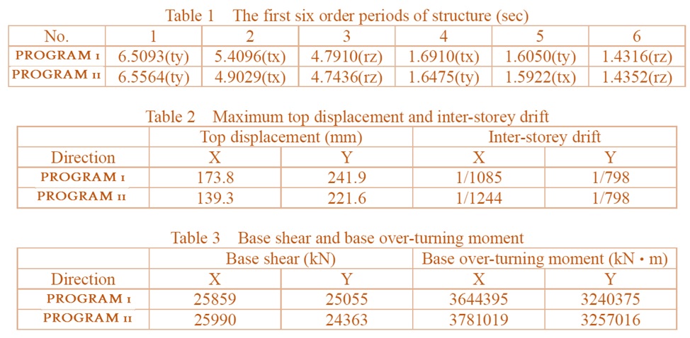
All these data indicate that the results of two programs are quite close, except that the X-directional stiffness of structure calculated by two programs has relatively differences. The writers consider that the differences are caused by different wall models of two programs. Generally speaking, this comparison validates the correctness of the analytical model. And for simplicity, the following comparisons are only related to the results of others.
Elastic time-history analysis
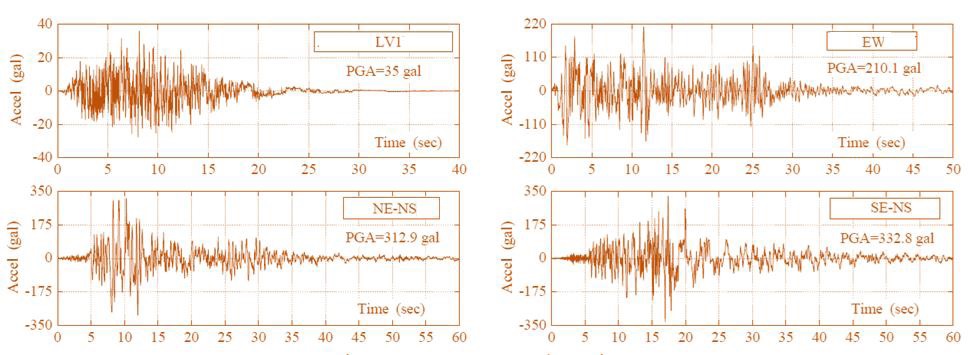
As a supplement of elastic response spectrum analysis, it is necessary for super high-rise building to perform elastic time-history analysis under frequent earthquake. This paper chooses one artificial wave, which is synthesized according to the standard response spectrum, and three natural earthquake records (measurements synchronized), which are EW, NE-NS, and SE-NS. And the latter two are the records of critical data of earthquake. According to the standard response spectrum, and three natural earthquake records. The waves are shown in Fig. 2. corresponding frequent earthquake, the peak ground acceleration of the construction site is 35 gal. Hence, scaling the three natural records to be compatible with frequent earthquake is necessary. Fig. 3 shows the acceleration response spectra of the artificial record and scaled natural records for frequent earthquake. And Fig.4 indicates the average acceleration response spectrum of the four input ground motions and the standard acceleration spectrum. These two figures bear out that the average response spectrum of ground motions matches the standard response spectrum in a statistical sense.

| Fig. 3 Acceleration spectra for frequent earthquake (4% damping) | Fig. 4 Average acceleration response spectrum and stand spectrum (4% damping) |
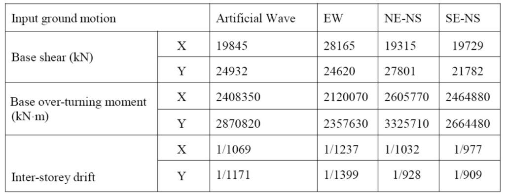
Using the results of response spectra design, such as the size of reinforcement members, the three-dimensional structural model is built by the program. Based on some simplification and assumptions, the elastic time-history analysis is performed. Some responses of structure are obtained which are presented in Table 4. Comparing these responses with those of response spectrum analysis, it can be found that they are compatible in average sense. So, we can utilize the envelope responses of time-history analyses and response spectrum analysis to fulfill the elastic seismic design.
Table 4: Responses of elastic dynamic analysis
NONLINEAR ANALYSIS
Since, the measurements out-of-codes high-rise building, it is necessary to perform nonlinear analyses to evaluate the seismic performance of the structure under fortifiable and severe earthquake. This paper adopts static and dynamic nonlinear procedure to investigate the structural behavior by using the program, which has been developed for more than twenty years.
In the nonlinear analysis course, there are some assumptions and considerations. The fixing point of structure is in the underground first floor (B1F). Using rigid diaphragm assumption, so the DOFs of beam elements and floors are reduced. Core walls are simplified to bidirectional in-plane column elements, working together with the Steel reinforced concrete columns in core walls by the assumption of plane-section. Furthermore, elasto-plastic uniaxial springs: rotation springs at element-ends, shear spring located in mid-span, are used to simulate the plastic hinges. Column elements have bending, shear, and axial deformations, also using uniaxial spring model for its computational efficiency. The nonlinear flexural and shear deformations of reinforced concrete elements, considering concrete cracking, use restoring force model having trilinear skeleton curve. Steel beams and concrete-filled square steel tubular columns use trilinear hysteresis model to express flexural deformation. The shear deformation of steel beams use degrading bilinear model. The nonlinear flexural deformations of Steel reinforced concrete elements make use of quadri-linear restoring force model. And the nonlinear axial deformations of peripheral core walls under the interaction of axial force and bending moment use asymmetric restoring force models to present axial stiffness degradation.
Moreover, seismic performance objective is established. Under fortifiable earthquake, the limbs of core walls do not appear the whole tension, and all the vertical members do not yield. The inter-storey drift values don’t exceed 1/200. Under severe earthquake, the limbs of core walls do not present shear failure. The inter-storey drift values don’t exceed 1/120.
Nonlinear static analysis
Nonlinear static analysis, also called pushover analysis, is a simplified methodology to evaluate structural inelastic behavior by applying monotonically increased lateral loads to every floor. The applied lateral load patterns have studied by many researchers. This paper applies the lateral load based on seismic storey shear according to the response spectrum analysis. By carrying out pushover analyses respectively along X- and Y-direction, the relationships of inter-storey drifts and storey shears are achieved. Fig. 5 shows the storey performance curves.
From this family curves we can simply estimate that there are no obviously weak stories in the structure. And it is also found that the Y-directional ductility of the whole structure is better than the X-direction, because the X-directional core walls are coupled shear walls while the Y-direction has several pieces of solid shear walls. Hence, the carrying capacities of structure along two directions are different. Then finding the limited values: 1/200, 1/120, corresponding fortifiable and severe earthquake, and its relevant storey shear, which appears firstly, the other stories’ inter-storey drifts and storey shears at the certain step can be obtained. Drawing these points at the storey performance curves, the distribution of inter-storey drifts is achieved, from which we can find that the maximum inter-storey drift of X-direction is located in 20F-21F and that of Y-direction is in 42F-43F.
Investigating the detailed damage information of elements, it is found that when the maximum inter-storey drift reaches 1/120 there is no shear failure. And the important failure model is embodied in bending yield of coupling beams.

X-directional Pushover Y-directional Pushover
Fig. 5 The Storey Performance Curves
Nonlinear dynamic analysis
Nonlinear dynamic analysis can show all kinds of responses of structure under fortifiable (LV2) and severe (LV3) earthquake by inputting ground motions at the fixing point. Besides the aforementioned three natural records, here are the other two artificial records shown in Fig.6. The peak ground acceleration corresponding LV2 and LV3 are 100gal and 220gal respectively. When calculating, Newmark’s numerical integration method is utilized, and the time interval is set to be 0.005 second. The viscous damping matrix is assumed to be Rayleigh’s damping, and the modal damping ratio is 4%.

By calculation, the responses of structure are obtained, among which the maximum inter-storey drifts under LV2 and LV3 are shown in Table 5 and the distribution of extreme inter-storey drift along the height is indicated in Fig. 7. Observing the envelope of extreme inter-storey drifts under four input ground motions, it can be found that the locations where the maximum inter-storey drift is obtained are almost identical with pushover analysis. This testifies, from one aspect, that the selection of input ground motions is reasonable and the results of static and dynamic methods are comparable. Moreover, under fortifiable earthquake (LV2), many coupling beams yield due to flexure, but most of the ductility ratios are less than 3.0. All the vertical members do not yield. Under severe earthquake, almost all coupling beams appear flexural yielding, and some ductility ratios exceed 6.0. Some frame beams located under 27F appear slightly flexural yielding. And the outside of core walls present partly local flexural yielding; the corner of core walls located in the bottom show yielding because of flexural tension. Generally, the structure does not appear shear failure, and the building shows well seismic performance.
On the other hand, some key members of the structure, such as the ground floor columns, the inclined columns between 28F to 30F, and the slender columns located in hotel lobby, are checked carefully under fortifiable earthquake. Examining the responses of frame columns under fortifiable earthquake, it can be found that the key columns at the middle part of building only show concrete cracking due to bending, some of which accompanying shear cracking, while the ground floor columns are in elastic state without cracking and yielding.
To conclude, responses of the structure, calculated by nonlinear procedure, indicate that the structure can satisfy the performance objective.
Table 5: Maximum Inter-Storey Drift


ASSUMPTIONS
The design procedure of a super high-rise structure. Elastic analysis including response spectrum method and elastic time-history analysis, and nonlinear analyses including static and dynamic procedures are conducted. There are some conclusions can be drawn:
(1) The results of elastic response spectra analyses calculated by two structural programs show the correctness of the calculating model. And the results of elastic time-history are basically identical with that of response spectra analyses.
(2) Nonlinear elasto-plastic analyses under fortifiable and severe earthquake are performed to indicate the behavior of structure. The results show that the structure has well seismic performance and achieves the performance objective.
Authored By:

Analysis of Seismic Design of Super High-Rise Structures
THE MAIN CONTENT OF TALL BUILDING SEISMIC ANALYSIS AND DESIGN
SOME OF THE PROBLEMS IN SEISMIC DESIGN OF HIGH-RISE STRUCTURES
TRENDS IN HIGH-RISE BUILDINGS SEIMIC ANALYSIS AND DESIGN
ELASTIC ANALYSIS
NONLINEAR ANALYSIS