


Ground improvement and ground modification refer to the improvement in or modification to the engineering properties of soil that are carried out at a site where the soil in its natural state does not possess properties that are adequate to withstand the load of the structure. The improvement may be accomplished by drainage, compaction, preloading, reinforcement, and grouting, electrical, chemical or thermal methods. Among the various soil stabilization procedures, the most suitable one is selected depending upon the type of soil available, time, cost involved etc.
Given below are some ground improvements techniques adopted.
Vibro compaction
Vibro Compaction is an established ground improvement method for stabilising granular soils such as loose sands, gravels and some hydraulic fills. The technique is primarily used for seismic mitigation and in-situ densification of loose sands up to 30m deep.The water jetting and horizontal vibratory action of the vibroflot acts to compact the loose soils into a denser condition and significantly improve the bearing capacity of the treated ground. The vibro compaction technique is well established for use in tank farm, port and marine structure projects.
Vibro Compaction significantly reduces the threat of liquefaction in the event of earthquakes; densifying sands to provide a firm founding layer It is extremely effective for sand compaction and land reclamation projects. Vibro Compaction provides fast, in-situ densification of loose sands to depths of up to 30 metres and is one of the most economical and sustainable ground improvement methods available, with no spoil generated and no fill material required.
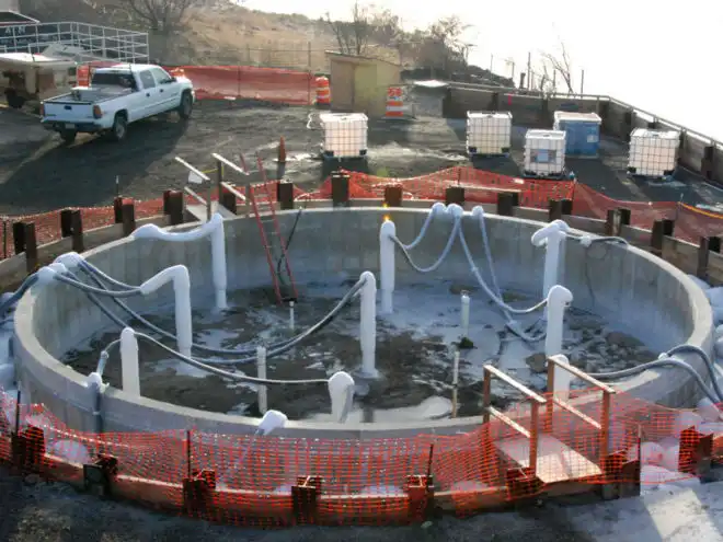
Vacuum consolidation is a soft soil improvement method that has been successfully used by geotechnical engineers and specialists of ground improvement companies. It does not necessarily require surcharge fill and vacuum loads of 80kPa or greater can, typically, be maintained for as long as required. However, if loads of 80kPa or greater are needed in order to achieve the target soil improvement, additional surcharge may be placed on top of the vacuum system. The vacuum preloading method is cheaper and faster than the fill surcharge method for an equivalent load in suitable areas. Where the underlying ground consists of permeable materials, such as sand or sandy clay, the cost of the technique will be significantly increased due to the requirement of cut-off walls into non-permeable layers to seal off the vacuum.
Various vacuum consolidation systems are developed for a number of applications. As the primary application of the vacuum consolidation method is consolidation and stabilization of soft clayey ground. When the vacuum consolidation method is extended to other applications with different working conditions and different treated materials, the systems require specific features and/or special designed construction machines. Moreover, vacuum consolidation applied in on-land and under-water conditions are principally different in equivalent load as the vacuum is applied on ground surface or under water table, relatively.
Soil Preloading
Depending on how a preload is applied, the preloading methods can be subdivided into preloading using fill, preloading using vacuum pressure and combined fill, and vacuum preloading methods. In addition to preloading, PVDs have also been used for some other relatively new methods such as dynamic consolidation for clays. In both cases, the main purpose of using PVDs is to reduce the drainage path so that the time taken for the consolidation of soft soil or the dissipation of excess pore-water pressure can be substantially reduced.
According to the soil classification system adopted by TC211 (Chu et al., 2009c), soil improvement through consolidation or preloading belongs to the category of ‘ground improvement without admixtures in cohesive soils’. This category is further divided into the following seven subcategories-
- replacement/displacement (including load reduction using lightweight materials)
- preloading using fill (including the use of vertical drains)
- preloading using vacuum (including combined fill and vacuum)
- dynamic consolidation with enhanced drainage (including the use of vacuum)
- electro-osmosis or electro-kinetic consolidation
- thermal stabilisation using heating or freezing
- hydro-blasting compaction.
Soil vitrification
Soil Vitrification technique uses heat to melt and then solidify harmful chemicals in a solid mass of glasslike material. It can be applied both in-situ (in-situ vitrification or ISV) and above ground in a treatment unit (ex-situ).
ISV uses space and an electrical current is passed between them, melting the soil between them. ISV uses very high temperatures (1,600 to 2,000 °C or a pair of, 900 to 3,650 °F). Melting starts close to the bottom surface and moves down. Because the soil melts, the electrodes sink additional into the bottom inflicting deeper soil to soften. Once the facility is turned off, the unfrozen soil cools and vitrifies, which implies it turns into a solid block of glass-like material. The electrodes become a part of the block. This causes the bottom exterior within the space to sink slightly. To level it, the sunken space is full of clean soil.
Ex-situ vitrification is far like ISV, except that it’s done within a compartment. Heating devices embody plasma torches and electrical transference furnaces. With plasma torch technology, waste is fed into a rotating hearth; the waste and melted material square measure control aligned with the aspect by force. Throughout the rotation, the waste moves through plasma generated by a standstill torch. To get rid of the melted material from the chamber, the earth’s rotation slows and also the dross flows through an underneath gap. Effluent gases square measure usually unbroken in an exceedingly separate instrumentation wherever high temperatures combust/oxidize the contents.
Ground freezing
Ground freezing is a construction technique used in circumstances where soil needs to be stabilized so it will not collapse next to excavations, or to prevent contaminants spilled into soil from being leached away.Ground freezing has been used for at least one hundred years. Ground freezing is also used to provide regional groundwater barriers around mining operations for gold and other minerals, oil sands or oil shales. It is often referred to as ground freezing, soil freezing, or freeze wall. The ground freezing process involves drilling and installing a series of relatively closely spaced pipes and circulating a coolant through these pipes. The refrigerated coolant extracts heat from the ground, converting the soil pore water to ice resulting in an extremely strong, impermeable material. It is the most positive method of ground improvement used in the underground construction and mining industries.
Deep shafts are the most common application of ground freezing. The freeze pipes are drilled and installed around the perimeter of the proposed shaft to do the required depth. The circulation of the coolant is initiated until a frozen zone ranging from 1 to ten meters is formed. The inside of the shaft is then excavated and lined and the freezing system turned off. Ground freezing is used extensively in the tunneling industry. Tunnel applications use several different approaches. The most common involves horizontally drilling the freeze pipes around the tunnel perimeter very similar to the frozen shaft approach.
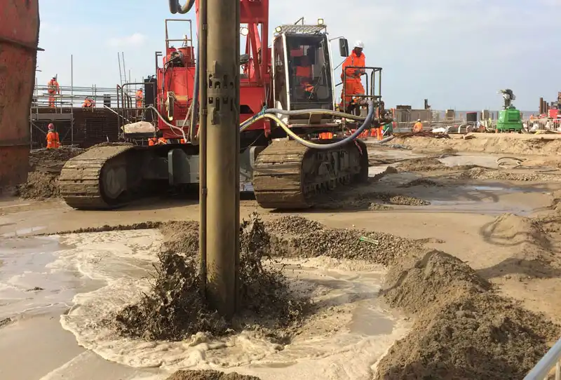
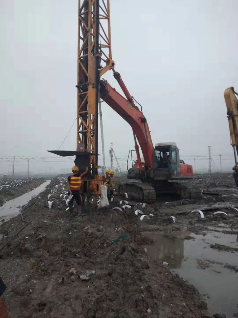
Vibro stone columns
Vibro stone columns or aggregate piers are an array of crushed stone pillars placed with a vibrating tool into the soil below a proposed structure. This method of ground improvement is also called vibro replacement. Such techniques increase the load bearing capacity and drainage of the soil while reducing settlement and liquefaction potential. Stone columns are made across the area to be improved in a triangular or rectangular grid pattern.
Column depth depends on local soil strata, and usually penetrates weak soil. During construction, a vibrating tool suspended from a crane penetrates to the design depth by means of its own weight and vibrations. Predrilling may be required in dense soil or may be used to reduce the amount of ground displacement during installation. Crushed stone is introduced into the hole by one of two methods. In the dry bottom method, a pipe attached to the vibrator supplies stone directly to it. In the wet top method, water jets located in the vibrator’s tip create an annular space around the vibrator through which stone is introduced from the top.

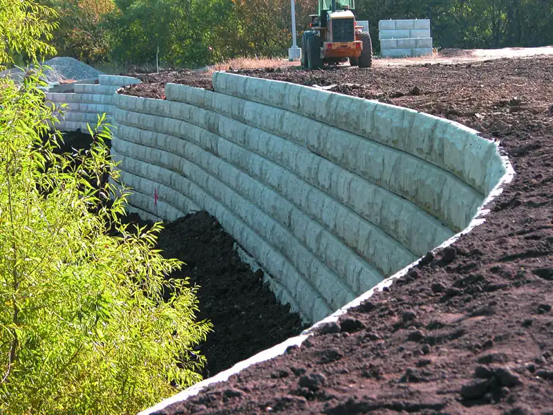
Mechanically stabilized earth (MSE)
Mechanically stabilized earth (MSE or reinforced soil) is soil constructed with artificial reinforcing. It can be used for retaining walls, bridge abutments, seawalls, and dikes.[ Although the basic principles of MSE have been used throughout history.
MSE walls stabilize unstable slopes and retain the soil on steep slopes and under crest loads. The wall face is often of precast, segmental blocks, panels or geocells that can tolerate some differential movement. The walls are infilled with granular soil, with or without reinforcement, while retaining the backfill soil. Reinforced walls utilize horizontal layers typically of geogrids. The reinforced soil mass, along with the facing, forms the wall. In many types of MSE’s, each vertical fascia row is inset, thereby providing individual cells that can be infilled with topsoil and planted with vegetation to create a green wall. The main advantages of MSE walls compared to conventional reinforced concrete walls are their ease of installation and quick construction. They do not require formwork or curing and each layer is structurally sound as it is laid, reducing the need for support, scaffolding or cranes. They also do not require additional work on the facing.
In a typical MSE wall, compacted granular soil is reinforced by horizontal layers of steel strips or geosynthetic materials. The use of reinforced elements significantly increases the strength of the system. Facing elements are relatively thin components, usually made out of precast concrete, welded wire mesh panels or shotcrete. Their structural objective is to hold the soil between the reinforcement layers. A facing system enables the construction of a steep or even a vertical MSE wall. Soil material is also placed without a reinforcement between the stabilized zone and the natural surface of the ground. This zone is known as retained backfill. A complete MSE wall is a gravity-based structure. It relies on its mass to bear the applied forces including lateral earth pressures, water pressures, seismic loads or loads related to human activity.
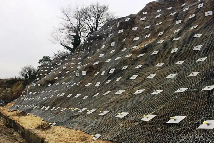
Soil nailing
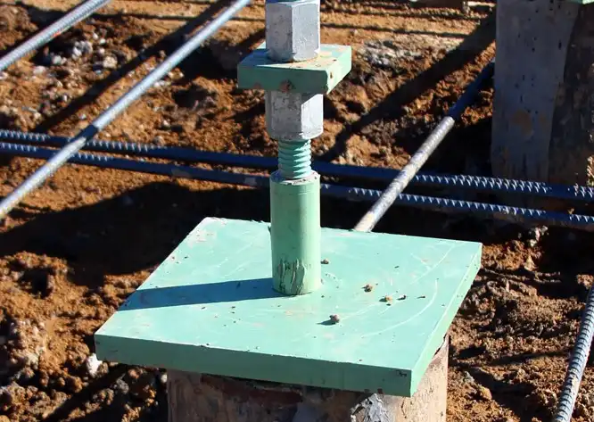
Soil nailing is a ground stabilisation technique that can be used on either natural or excavated slopes. It involves drilling holes for steel bars to be inserted into a slope face which are then grouted in place. Mesh is attached to the bar ends to hold the slope face in position. They are commonly used as a remedial measure to stabilise embankment
Soil nailing uses grouted, tension-resisting steel elements (nails) to reinforce in situ soils and creates a gravity retaining wall for permanent or temporary excavation support.Soil nail walls are generally constructed from the top down. Typically, soil is excavated in three to six feet deep stages. After each excavation stage, near-horizontal holes are drilled into the exposed face at typically three to six foot centres. Tension-resisting steel bars are inserted into the holes and grouted in place. A drainage system is installed on the exposed face, followed by the application of reinforced shotcrete wall facing. Precast face panels can also be used. Bearing plates are then fixed to the heads of the soil nails. This installation process is repeated until the design wall depth is reached. The finished soil nails then produce a zone of reinforced ground.
Micropiles
Micropiles are high-performance, high-capacity drilled deep foundation elements typically between 5–12 inches in diameter that can extend to depths of 200 feet and achieve working loads of over 200 tons. Micropiles are composed of high-strength steel casing, rebar and grout.
Micropiles are small diameter drilled and grouted friction piles. Each pile includes steel elements that are bonded into the bearing soil or rock – usually with cement grout. The bearing stratum is logged during installation drilling to assure that bearing capacity is adequate. Micropiles do not rely on end-bearing capacity, so there is no need to establish the competency of rock beyond bond-depth. They can be installed quickly in virtually every type of ground using highly adaptable mobile drilling equipment.Micropiles can be used in a variety of foundation projects. They are particularly useful when projects are in areas with limited access or weak soil. They have become a preferred method of deep-foundation stabilization thanks to their reliability, versatility, and efficiency.
Grouting
Grouting is quite a well-known technique in the field of civil engineering, especially in foundation engineering. Grouting is effective in both sand and silt deposits. Grouts are liquid suspensions or solutions that are injected into the soil mass to improve its behaviour. Such liquids can permeate into the void space of the soil and bind the soil particles together. The primary purpose of grouting is to fill the voids of the formation material by replacing the existing fluids with the grout and thereby improving the engineering properties of the medium, especially reducing the permeability. The selection of proper grouting materials depends upon the type of granular medium and the purpose of grouting. Cement, Bentonite, clay and lime are the grouting materials normally used for grouting a granular medium. In the present paper, sand was used as the grouting medium and cement was used as the grouting materials.
Grouting is effective in both sand and silt deposits. Grouts are liquid suspensions or solutions that are injected into the soil mass to improve its behavior. Such liquids can permeate into the void space of the soil and bind the soil particles together. The primary purpose of grouting is to fill the voids of the formation material by replacing the existing fluids with the grout and thereby improving the engineering properties of the medium, especially reducing the permeability.
Conclusion
These are various methods available for soil improvement techniques which will be used for the needs of accelerating bearing capability, enhancing shear strength and decreasing consolidation settlement of saturated medium clay such as soil replacement, preloading with vertical drains, stone columns, stabilization with additives and thermal ways.
Source- Irjet.net, .ijesi.org, semanticscholar.org, Balfourbeatty.com, rembco.com, iadc-dredging.com, vibromenard.co.uk, pinterest.com, groundfreezing.com, menardgroupusa.com, en.wikipedia.org, designingbuildings.co.uk
